Ammeters and voltmeters are the most basic electrical instruments you will see in any school level laboratory or gadgets workshop. Previously we have covered the former, and today we will cover what is a voltmeter, why do we use it, how it works, and what types of voltmeters are out there.
Definition of a Voltmeter
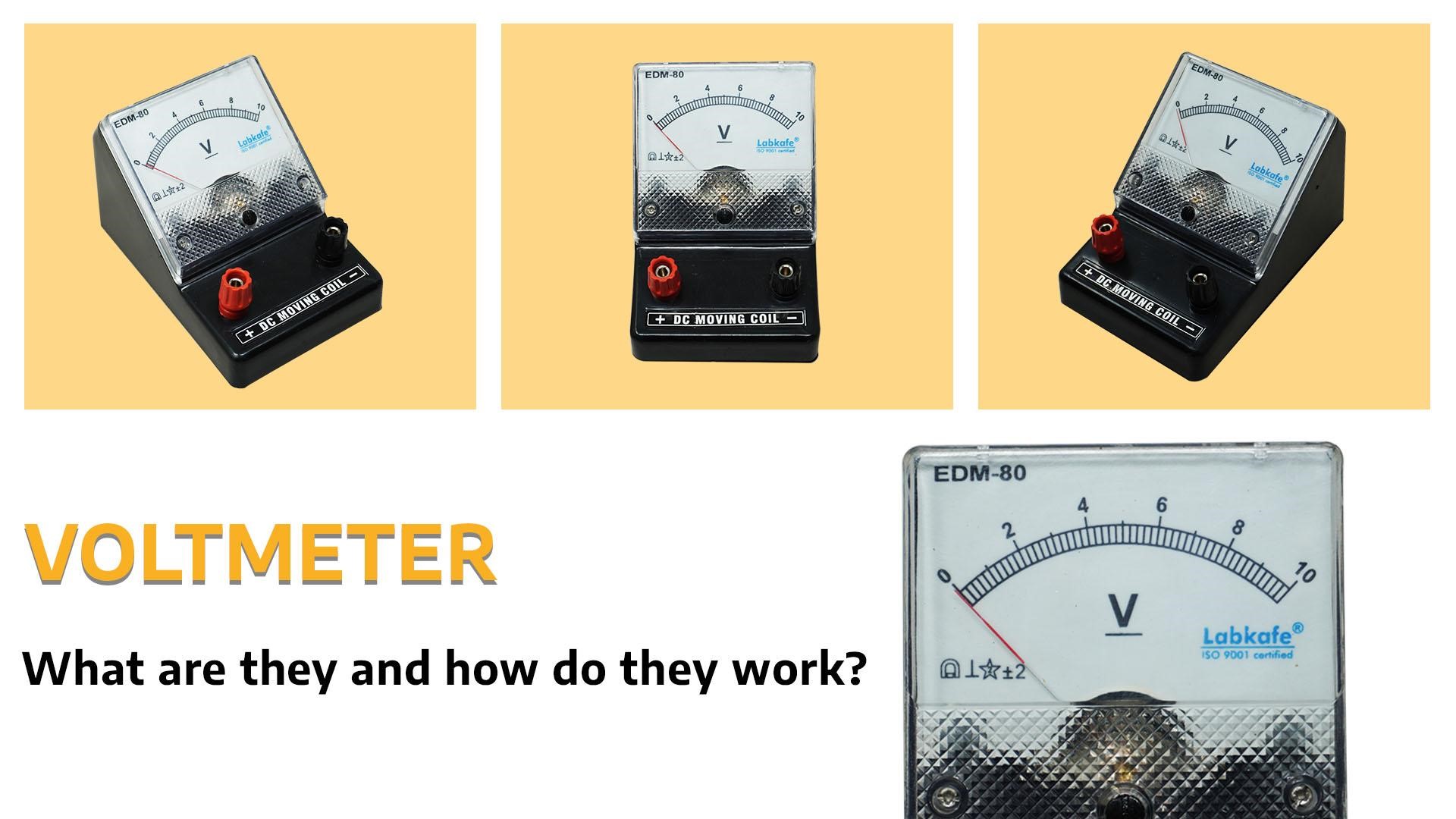
A voltmeter is an instrument for measuring the electrical potential difference between two points in a circuit. At the most basic level, it is a galvanometer with a resistance in series. The meter displays the potential difference across a part of the circuit in different denominations of Volts, therefore the name “voltmeter” came about.
A voltmeter is basically a movable coil or similar mechanism inside a magnet’s two poles. The moving structure inside also mounts a needle or pointer or a sensor on it, which allows us to read the value of the deflection of that moving part (due to the magnetic field). In size and capacity, they can vary a lot ‒ there are small, light ones used in labs and electronics workshops, and there are big solid ones attached to heavy-duty generators and transformers. And then there are those seriously high-powered ones we can see in the electricity stations, capable of measuring several thousand volts!
Voltmeter Working Principle
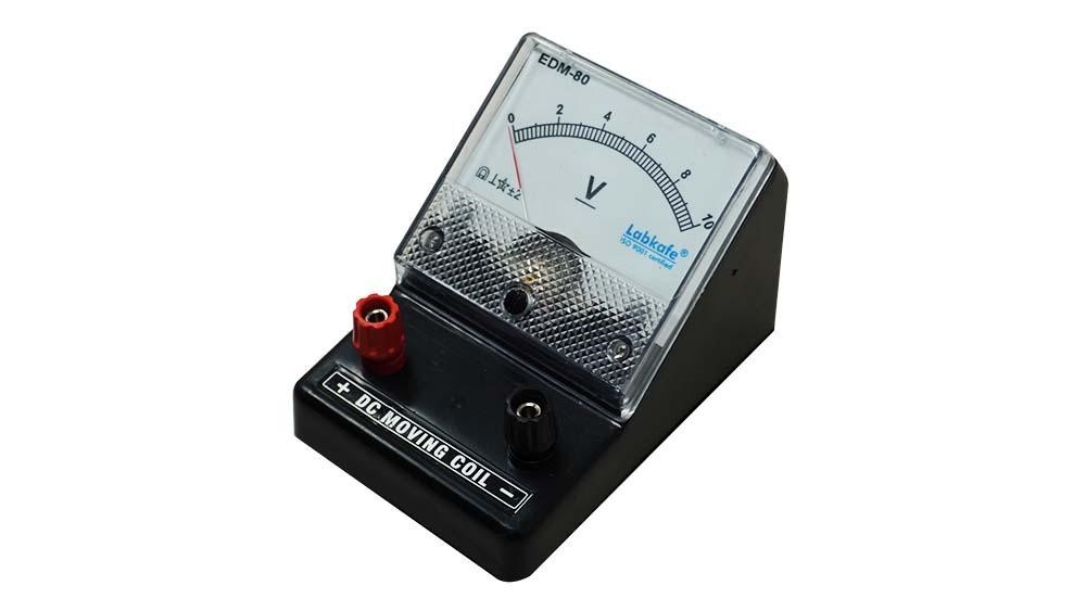
The idea of a voltmeter is to couple a galvanometer with a high resistance. Since the galvanometer detects the presence of electricity in a circuit that it is also a part of, the series resistance makes the couple what we essentially call a voltmeter. As the series resistance lets very little current flow through the galvanometer, the deflection of its needle will indicate the voltage drop across the meter-resistance couple (derived from the V=IR equation). An ideal voltmeter, of course, has infinite resistance.
Due to this arrangement as above, we must use a voltmeter only in parallel to the actual circuit. Just attach the voltmeter terminals (they have no polarity, so use any) to the points across which you want to see the voltage, and the meter will show you. Provided, of course, it has the right denomination.
Another thing. An ammeter can measure the current running throughout the whole circuit. But a voltmeter can judge the voltage drop across only two points you choose. This is because an ammeter becomes part of the circuit, but a voltmeter doesn’t ‒ it sits outside the main circuit.
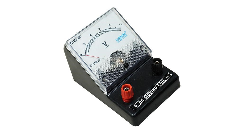
In most analog voltmeters, the instrument is built like the following: there is a large, hollow magnet and inside its pit (between the poles) there sits a spiral spring mounted on a spindle. There is also a coil of fine wire attached to the spindle so that when it moves, the spring gets wound. The needle of the meter is also attached to this assembly.
So, when a current passes through the wire coil, it produces an electromagnetic field, which in turn is pushed by the big magnet’s own permanent magnetic field. So the coil moves and it moves the needle with it, which shows the reading on a mounted, calibrated scale. When you break the circuit, the coil loses its magnetic field and the energy in the wound-up spring helps to bring it back into the original (zero) position.
Types of Voltmeters
Depending upon usage, there are many types of voltmeters that we see in most labs, workshops, and electricity generation and circulation centers. The most common of them are as follows:
Standard DC Voltmeter
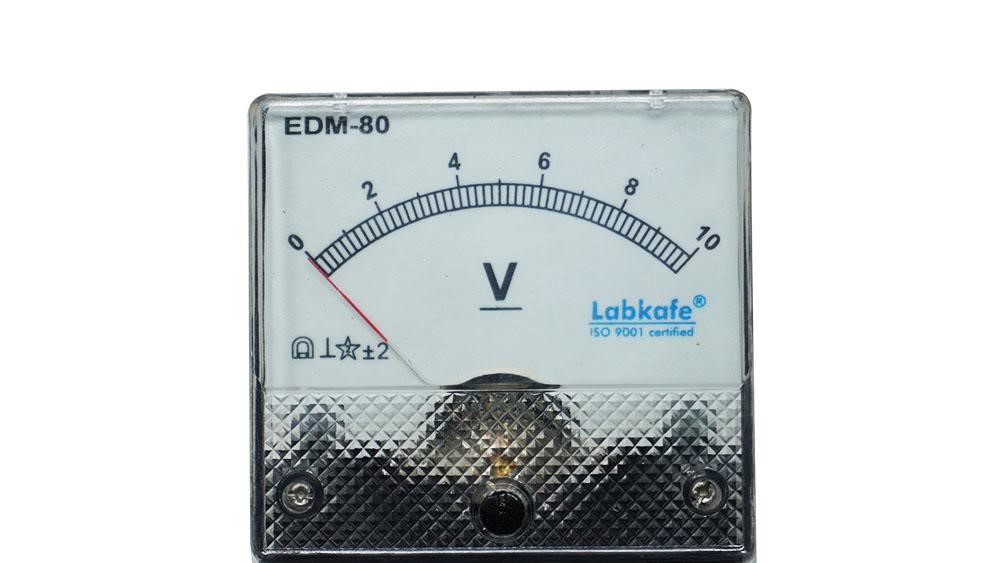
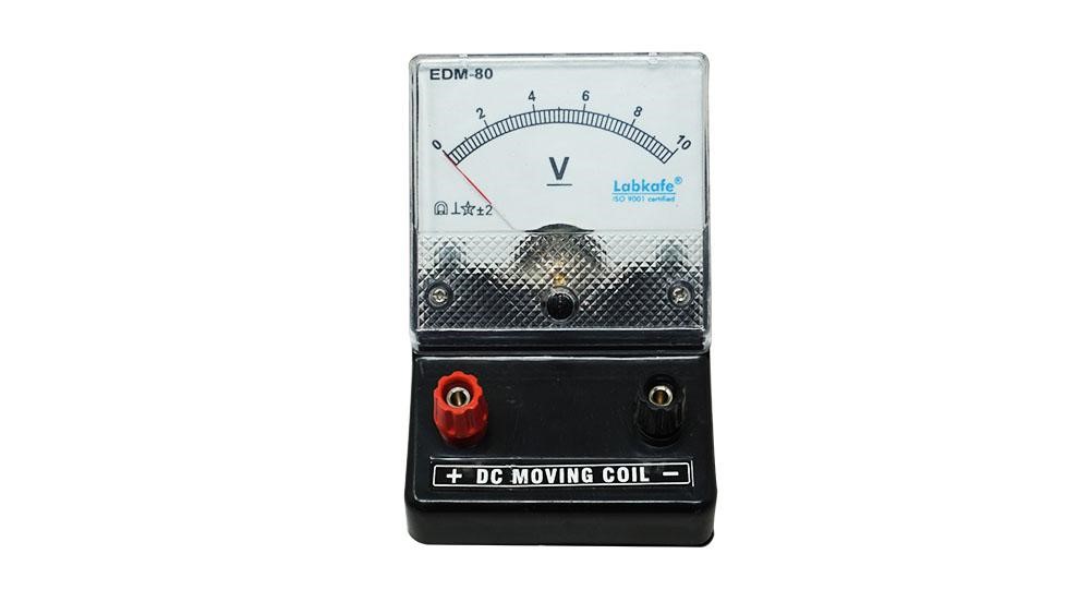
All circuits that do not work with the main supply line mostly run on DC electricity. To work with these circuits, we need a standard DC voltmeter. You can see these most commonly found voltmeters everywhere ‒ in schools or colleges in physics or electronics labs, in electronics workshops, even in car repair garages. In schools, analog voltmeters are used which can measure from 0 to 10 volts, since that’s all the power we use in school lab electronics. In electronics or electrical shops, you will see various multimeters with a lot more capability.
Amplified Voltmeter
Also known as milli-voltmeters or micro-voltmeters, these are sensitive instruments, capable of detecting minute levels of potential drop. Basically, there is an electronic amplifier sitting in the input line of these voltmeters, increasing the amplitude of the incoming electricity many times so that a normal voltmeter can be used to measure the effect. You can see these in special labs and workshops only.
Digital Voltmeter
Everything is going digital these days, why not voltmeters too? The basic idea here is to record the deflection of the moving coil (as we mentioned above), and then to run it through an analog-to-digital converter. The result shows up in readable numbers in an electronic display.
Most workplaces these days use digital voltmeters. With electricians, factory, and repair people, they actually use a multimeter that combines the capabilities of ammeters and voltmeters, and they are mostly digital. Digital voltmeters tend to be more reliable than analog ones due to being more sturdy and having fewer moving parts.
AC Voltmeters
Generally most voltmeters you’ll get to use in everyday life and in workshops or labs are DC voltmeters, meaning they work in a direct current circuit only. But when you need to measure potential difference across circuits with alternating current, you will need an AC Voltmeter. It is nothing but a standard voltmeter with a rectifier fixed into the input line. The rectifier converts the AC to almost-DC electric and so the voltmeter reflects the average voltage.
Conclusion
A Voltmeter, or a voltage meter, can tell you the potential difference between two points in a given circuit. They can be small or large; measuring from microvolts to kilovolts. At least one voltmeter is a part of every school physics lab package for doing electronics practicals. You can do experiments with diodes and resistors with a voltmeter.


Leave a Reply