Aim:
To measure (a) diameter of a given wire (b) thickness of a given sheet and (c) volume of an irregular lamina using screw gauge.
Apparatus:
- Screw Gauge
- Any Wire
- Metallic Sheet
- Irregular Lamina (uniform thickness)
- Millimetre Graph Paper
Theory:
Using Vernier Callipers we can measure length accurately up to 0.1 mm. To measure more accurately, up to 0.01 mm or 0.005 mm, we use screw gauge. A Screw Gauge is an instrument of higher precision than a Vernier Callipers. In any ordinary screw, there are threads and the separation between any two consecutive threads is the same. The distance advanced by the screw when it makes its one complete rotation is the separation between two consecutive threads. This distance is called the Pitch (p) of the screw. It is usually 1 mm or 0.5 mm. Fig. 2.1 shows a screw gauge. It has a screw S which advances forward or backward as one rotates the head C through rachet R. There is a linear scale LS attached to limb D of the U frame.
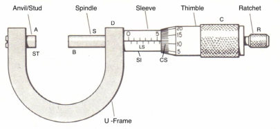
The smallest division on the linear scale is 1 mm (in one type of screw gauge). There is a circular scale CS on the head, which can be rotated. There are 50 or 100 divisions on the circular scale. When the end B of the screw touches the surface A of the stud/anvil ST, the zero marks on the main scale or pitch scale or linear scale LS and the circular scale should coincide with each other as shown in fig. 2.2.
Principle:
Pitch of the Screw Gauge
The linear distance covered by the tip of the screw (B) in every rotation of the circular scale is called the pitch of a screw gauge. This movement of the spindle is shown on an engraved linear millimeter scale on the sleeve. To find the pitch, give full rotation to the screw (say 4 times) and note the distance (d) advanced by the circular scale over the pitch scale.
If the distance d is 4 mm The pitch can be represented as:

Least Count of the Screw Gauge
On the thimble there is a circular scale which is divided into 50 or 100 equal parts. We are using a screw gauge which has 50 circular divisions. The Least count (LC) is the distance moved by the tip of the screw, when the screw is turned through 1 division of the circular. The least count can be calculated using the formula;

Determination of Zero Error:
When the stud and spindle are brought in contact with each other, the zero of circular scale should coincide with reference line of main scale. In that case the screw gauge have no zero error as shown in Fig. 2.2. However, when the zero of circular scale does not coincide with reference line of main scale, the screw gauge is said to have zero error.
The zero error is said to be positive zero error if on bringing the spindle in contact with stud, if the zero of the circular scale lies to the bottom of the reference line as shown in Fig. 2.3. Owing to this error, the measured readings will be systematically bigger than the actual value by the same amount. Hence the error is to be subtracted from the observed readings. If on the other hand, the zero of the circular scale lies to the top of the reference line as shown in Fig.2.3, it is said to be negative
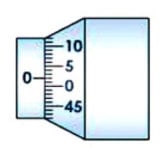
Fig. 2.2
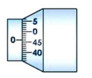
Fig 2.3
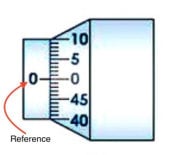
Fig 2.4
zero error. Owing to this error, the measured readings will be systematically smaller than the actual value by the same amount. Hence the error is to be added from the observed readings.
To determine the error, bring the spindle in contact with the stud and note the reading on the linear as well as circular scale. If the linear scale reading is x and circular scale reading is n’ then zero error is given by ± (x + n’ × LC ). Zero correction (e) is always negative of zero error. In our case, as shown in the fig. 2.3, the linear scale reading is zero and the circular scale zerois 2 divisions bellow the reference. Therefore, the zero error is: -[0 + 2 × 0.02] = – 0.04 mm.
So, the Zero correction (e) is = -[-0.04] = 0.04 mm.
Hence, the Actual reading = Measured reading – (±e)
= Measured reading – (-0.04) for positive error
Procedure:
- Find the value of one linear scale division (L.S.D.).
- Calculate the pitch and the least count of the screw gauge.
Measurement of diameter of the wire
- Bring the spindle B in contact with the stud A and calculate the zero error. If there is no zero error, then note down zero error nil.
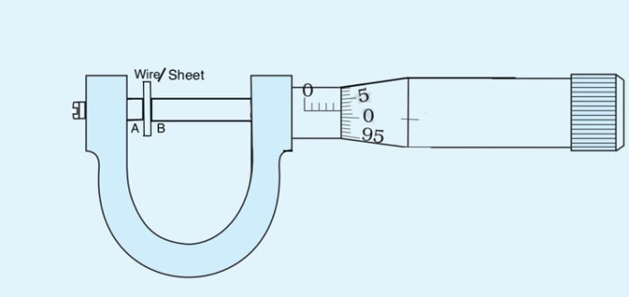
- Move the face B away from face A. Place the wire lengthwise (as shown in the fig.2.5) over face A and move the face B towards face A using the ratchet head R. Stop when R turns (slips) without moving the screw with click sound.
- Note the number of divisions of the main scale reading (M.S.R) visible before the edge of circular scale.
- Note the number (n) of the division of the circular scale lying over reference line.
- Repeat steps 5 and 6 after rotating the wire by 90° for measuring diameter in a perpendicular direction.
- Repeat steps 4, 5, 6 and 7 for five different positions separated equally throughout the length of the wire. Record the observations in table 2.1.
- Find observed diameter and apply zero correction in each case.
- Take mean of different values of actual diameter.
Measurement of thickness of a given sheet
- Repeat steps 1, 2, 3, 4, 5 and 6. Instead of wire place the rigid sheer between face A and B.
- Find the thickness of the sheet as shown in fig. 2.5 at five different position of the sheet, spread over the surface of the sheet.
- Record the observations in the table 2.2.
- Find the observed thickness and apply zero correction in each case.
- Take mean of different values of actual thickness.
Measurement of volume of an irregular lamina
- Repeat steps 1,2,3,4,5 and 6. Instead of wire place the lamina between face A and B.
- Find the thickness of the lamina as shown in fig. 2.5 at five different position of the lamina and record them in table 2.3.
- Place the lamina on a millimetre graph paper and draw the boundary of the area with a sharp pencil.
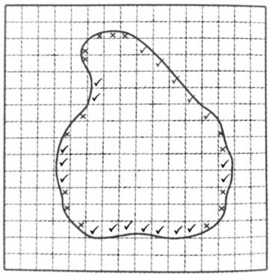
- Count the number of square enclosed by the boundary. The boundary may contain fractions of many squares. Count those squares, which have fractions greater than half within the boundary as a full squares and ignore those which have less than half within the boundary as shown in the fig 2.6. Naturally there could be some compensation and the result will be very near to the actual value.
Observation:
Determination of least count:
One linear scale division, L.S.D. = ____ mm
Total number of divisions is the in circular scale, N = _______
Distance moved by the screw for 4 rotations, d = ________ mm
Pitch of the screw, p = 4/d = ____mm
Therefore, Least Count, L.C. = p/N= ____mm
Zero error or Instrumental error with the sign:
Zero error, e = ± (x + n’ × LC ) = _______mm
Table 2.1 Determination of diameter of the wire:
| No of Obs. | M.S.R (M) mm | No of Circular scale division of the reference line (n) | Observed Diameter D0 = M + n × LC mm | Actual Diameter D = D0 – (± e ) mm |
| 1.(a) (b) | ||||
| 2.(a) (b) | ||||
| 3.(a) (b) | ||||
| 4.(a) (b) | ||||
| 5.(a) (b) | ||||
[(a) and (b) corresponds to mutually perpendicular diameters.]
Mean actual diameter, Dw : …………………………………… (mm)
Table 2.2 Determination of thickness of a sheet:
| No of Obs. | M.S.R (M) mm | No of Circular scale division of the reference line (n) | Observed Thickness T0 = M + n × LC mm | Actual Thickness T = T0 – (± e ) mm |
| 1. | ||||
| 2. | ||||
| 3. | ||||
| 4. | ||||
| 5. |
Mean actual thickness, Ts : …………………………………… (mm)
Table 2.3 Determination of thickness of an irregular lamina:
| No of Obs. | M.S.R (M) mm | No of Circular scale division of the reference line (n) | Observed Thickness T0 = M + n × LC mm | Actual Thickness T = T0 – (± e ) mm |
| 1. | ||||
| 2. | ||||
| 3. | ||||
| 4. | ||||
| 5. |
Mean actual thickness, TL : …………………………………… (mm)
Calculation:
Number of small squares enclosed by the boundary , NL = _______
Actual Thickness, TL = ___________ mm
Area of the lamina, A = NL × 1 mm2 = _________mm2
Therefore, the volume of the lamina, V = A × TL = …………………………..mm3
Precautions:
- The wire should not be pressed tightly between stud and spindle.
- Instrumental error should be determined and necessary correction should be taken.
- Repeated readings are necessary at different places to ensure uniformity of the wire.
- Diameter should be measured in one direction and then in perpendicular direction at the same place, to see whether it is uniform.
- Parallax error should take care of.
- The Milled head is always to be turned in the same direction, otherwise back-lash error will occur.
Sources of Error:
- There might be friction in the screw.
- Circular scale divisions may not be equally divided.
- There might not be uniformity in the wire.
- The sheet and lamina may not be of uniform thickness
Reference:
Your may checkout our blog on HOW TO USE VERNIER CALIPER TO FIND OUT LEAST COUNT AND MEASURE DIAMETER OF SPHERICAL BODY AND BEAKER
We are a School laboratory furniture and Lab equipment manufacturer and supplier. In laboratory furniture for school, we first design the entire laboratory room keeping in mind the requirements as per affiliation CBSE Bye-Laws. Also, we take care of the complete designing and installation of laboratory furniture.
In the lab equipment section, we have a wide range of glassware, chemicals, equipment and other lab accessories. Most of them are available for order online on our website but some of them can be procured on demand.
If you have need:-
- laboratory equipment or lab furniture requirements for school
- composite lab equipment list for school
- Physics lab equipment list for school
- Chemistry lab equipment list for
- Biology lab equipment list for school
- Pharmacy lab equipment
do drop a message through chat or mail us at [email protected] or call +919007218364 and we’ll get in touch with you.








Leave a Reply