How to Perform Ohm’s Law Experiment
| Objective: Study the dependence of potential difference (V) across a resistor on the current (I) passing through it and determine its resistance. (Ohm’s Law) |
One of the most common tasks you can face in the 10th-grade physics or science laboratory is to perform the Ohm’s Law Experiment. It is common in class IX or class X in most boards like CBSE, ICSE, state boards, and even in IGCSE or IB curriculums. This experiment is also there for certain class 12 syllabus.
We have covered the theory of Ohm’s law experiment before, now let’s move on to the practical session of verifying Ohm’s law. But first, let’s state Ohm’s law for convenience’s sake once.
Ohm’s Law
The current through a conductor between two points is directly proportional to the voltage across the two points.
Ohm’s Law Mathematical Expression
V = IR
Where,
- V = voltage across a given conductor
- I = current through the circuit
- R = resistance of the conductor
Base Idea of the Experiment
Here V would be measured across the conductor, and I would be measured in series to it. We will change the voltage, and record the current as a result. When we have a bunch of readings, we will plot the readings in a graph.
Our intention is to see if the graph would come out as close to a straight line as possible. That would mean that the resistance remained the same, denoting V was proportional to I. When we see that V and I are proportional, we will get the value of the resistance from the above formula.
The Experiment
Equipment
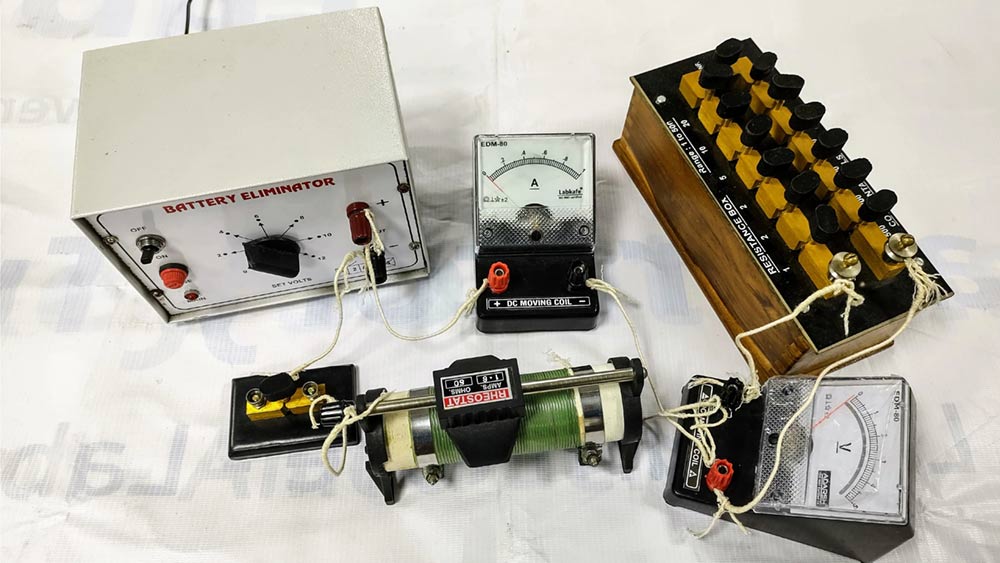
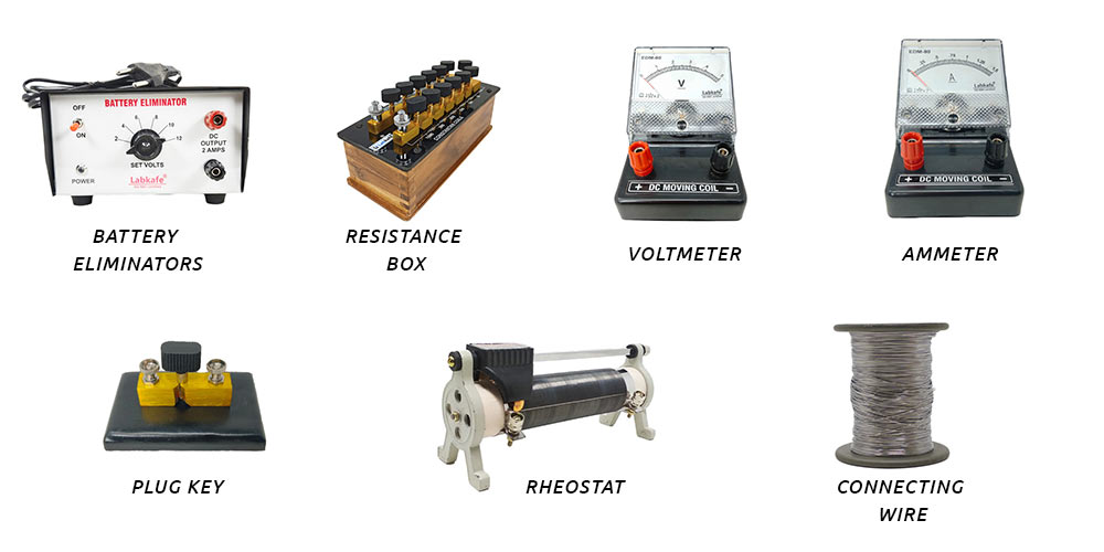
To perform the Ohm’s law experiment, you will need the following equipment:
- 1 battery eliminator (0-12 volts, 2 Amps)
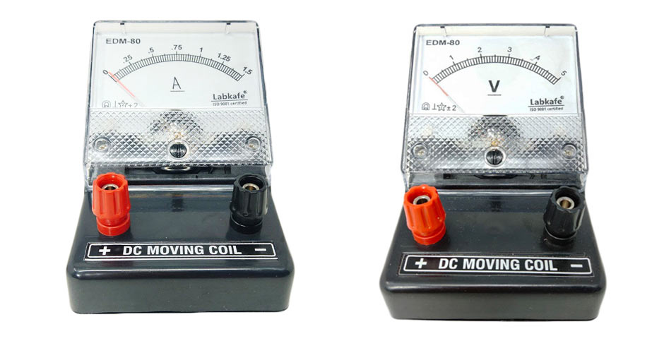
- 1 voltmeter
- 1 ammeter
- 1 rheostat
- 1 resistance box (or an unknown resistor)
- Connecting wires
You can find all of those in Labkafe’s Composite Lab Package or Physics Lab Package .
Procedure
We will need to build an electronic circuit with the battery and the resistor, through which the current is supposed to pass. To measure that current, you will need to connect the ammeter in between the battery and the resistor in series. And to measure the voltage, you will have to connect the voltmeter in parallel to the resistor.
- Why do you need to connect the ammeter in series?
- Since the ammeter measures the current passing through the circuit, that is why it has to be a part of the circuit itself. That means, you will have to connect the positive (red) pole of the battery to the negative (black) pole of the ammeter, and connect the positive pole of the ammeter to the rest of the circuit. Since an ideal ammeter has ZERO resistance, we can assume that there will be no loss of current across the ammeter itself.
Read more: how does an ammeter work?
- Why do you need to connect the voltmeter in parallel?
- A voltmeter is supposed to measure the potential difference between two points in a circuit. Therefore, the voltmeter needs to touch those two points simultaneously with its two points, making a parallel circuit with that part of the system. Since an ideal voltmeter has INFINITE resistance, it will eat up next to no current across itself, making sure it does not influence the system.
Read more: working principles of a voltmeter
Ideally, we should be using a battery that can give different voltages that our experiment needs. But no batteries in reality do that. So, we will put a rheostat in series with the battery, which then we can use to control the voltage as we wish.
- How can a rheostat control the voltage when a resistor is supposed to change the current?
- A rheostat is also a resistor, just one that varies in power. So, you may naturally ask how a resistor is controlling voltage while they are supposed to control the current? The answer is quite simple ‒ just look again at the Ohm’s law formula. In “V = IR” we take R constant. But for a given, fixed value of current (keeping I constant), if we change the resistance value (varying R), the voltage V will change. This is a clever manipulation of Ohm’s law principle.
Even though our battery eliminator (which we are using instead of a real battery) can supply different amounts of voltage, we will keep it fixed at a constant voltage and use the rheostat to change the voltage. This will be as close to real-life as possible.
Setting Up
The circuit diagram for the Ohm’s law experiment is like the following:
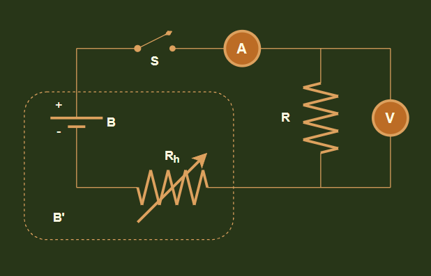
Where,
- A is the ammeter
- V is the voltmeter
- B is the battery
- Rh is the rheostat
- R is the resistor
- B’ is the virtual, variable battery we are creating by combining B and Rh
- S is a switch turning the circuit on and off (you may already have a switch in your battery eliminator to serve the same purpose)
(Note: the diagram in your textbook may differ somewhat from our diagram. But don’t worry, it will work out fine for our purpose.)
How to perform the experiment
- Connect the equipment as shown in the circuit diagram. Keep the switch off for now and the rheostat at the least position.
- Take a notebook and make two columns for voltage (V) and current (I).
- Turn on the switch.
- Observe the voltmeter and ammeter carefully. In the notebook, note down the values shown in the meters in the respective columns for V and I.
- Turn off the power and move the rheostat to change its resistance a little. This will change the reading in the voltmeter.
- Repeat steps 3, 4 and 5 a few more times till you get at least half a dozen different readings.
- Plot the V vs I graph in a fresh graph paper. What does the graph look like?
Interpreting the Results
We have performed the Ohm’s law experiment with our electronics lab package, and here is the result data as chart and graph:
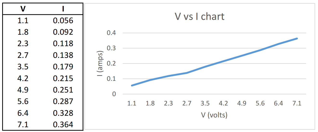
As you can see, the above data shows that the current rose steadily as the voltage increased and we had a pretty much straight lined graph. That means I was proportional to V. Proved!
Finding the resistance of the conductor
Since V = IR,
So, R = V/I
From the above results, we can figure the average voltage as, V = 3.96v
And the average current was, I = 0.203A
Therefore, the effective value of the resistor in the experiment would be:
R = V/I = 3.96/0.203 = 19.53Ω.
How accurate are the results of Ohm’s Law experiment?
In reality, we used a 19 ohms resistor for the experiment. The error (0.53 ohms) probably came due to:
- Heating issues during the Ohm’s law experiment
- Internal resistances of the voltmeter, ammeter, or other components
- The equipment being used not precisely perfect to theory
Do keep in mind that due to various natural issues it would be hard for you to get an accurate value of the resistor ‒ there can probably be a ~10% error margin. The older your equipment is, the more error you can expect.
All the equipment used in this experiment came from Labkafe’s standard composite lab package.


Leave a Reply